 1
 2
 3
 4
 5
 6
 7
 8
 9
10
11
12
13
14
15
|
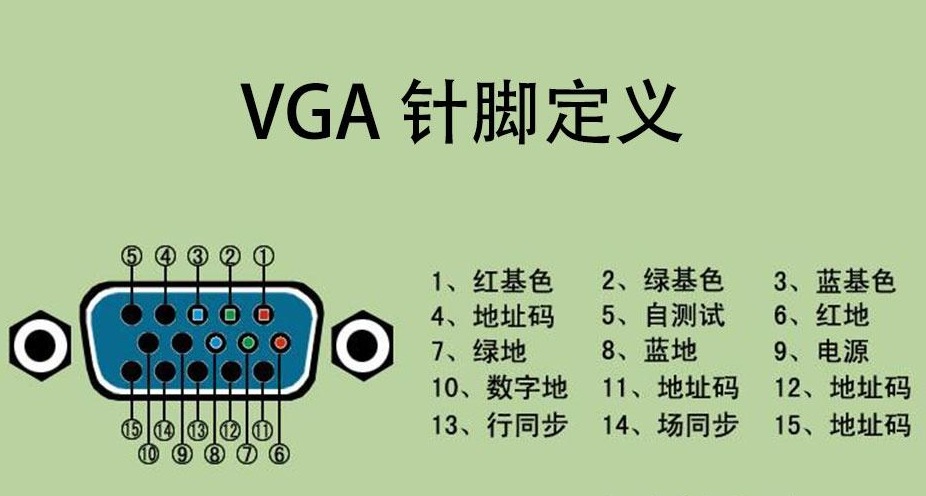
1. Red video (red wire)
2. Green video (light green wire)
3. Blue video (light blue wire)
4. ID Bit (sometimes RES, or monitor ID2)
5. Self-test (vendor-specific, often GND, black wire)
6. Red ground (4,6,7,8,11 are often tied together as shield)
7. Green ground
8. Blue ground
9. Reserved (vendor-specific, yellow wire)
10. Digital ground (red wire)
11. ID0 (monitor ID bit 0)
12. ID1 (monitor ID bit 1, green wire)
13. Horizontal sync (white wire)
14. Vertical sync (brown wire)
15. ID3 (or monitor ID bit 3, orange wire)
|